The Watchdog notes: throughout this article, as well as elsewhere on this website, the terms EVF (electronic viewfinder) and CVF (color viewfinder) are used interchangeably. Both acronyms refer to the same component.
A couple of months ago, Michael Pappas proposed: "For those who are handy, building a lipstick size adapter that the EVF plugs into, and the adapter plugs into the camera body, would not be difficult. This adapter would stop the flow of the color pins and let the Y channel pass through. As to the character data, these also could be stopped from passing through. The results would be a completely clear screen, void of data. Not every one wants this, but there are some of us that would like this option. Now if there were mini switches put on this adapter, one could switch between a color or B&W display and the same with the CG data too."
WARNING: Folks who try build or install one of these do so at their own risk. While the circuit I built worked on my camcorder, I can not vouch for the circuit someone else builds for your camcorder. While it may be possible to implement this circuit using the actual components from your camcorder, doing so will definitely invalidate your warranty and may cause other damage in the process.
The standard color viewfinder (CVF) for the Canon XL1 is a 180,000 pixel color LCD panel that is designed to provide about 350 lines of horizontal resolution. The CVF receives power and video signals from the camcorder body via a removable plug and cable. This cable also carries signals for the tally light and an IR remote receiver that are also mounted in the CVF assembly.
The video signals sent to the CVF are comprised of the following: a ‘Y' or B&W video signal, a ‘R-Y' and a ‘B-Y' which contain the color information, three leads that carry the R, B and G components for the character and icon signals that are displayed in the CVF, and a sync signal.
In principal, the display in the CVF can be made black and white by disconnecting the ‘R-Y' and ‘B-Y' signals. Also, the character and icon display can be suppressed (or color changed) by disconnecting the character generator signals. It should be pointed out that the zebra bars are in the video image and are not created by the character and icon generator.
However, it is not sufficient just to simply disconnect the lines that carry the color information to the CVF... because even with a B&W image, they provide a steady signal voltage to the viewfinder. Any B&W converter must ensure the CVF continues to receive the necessary signals for proper operation and it must minimize the possibility of unwanted stray signals.
A suggested approach is to place the necessary components in a small chassis with appropriate connectors that can be placed in between the CVF and the camera body. There are other, perhaps better ways to accomplish this task... however, this one works...
Circuit description.
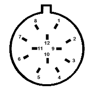
The CVF is connected to the camcorder body by a 12-conductor cable. Except as noted below, the twelve leads are connected through the adapter from the camcorder body to the CVF.
- Pin 1 provides 5 volts DC to the CVF.
- Pin 2 provides 'Y' luma signal, w/o sync.
- Pin 3 is a signal/power ground.
- Pins 4 & 5 carry the color component information.
- Pin 6 is the sync signal.
- Pins 7, 8, and 9 are the R, G, and B components of the CVF character and icon display.
- Pin 10 is part of the power supply circuits.
- Pins 11 and 12 carry signals for the tally light and IR remote sensor.
The switch SW1 disconnects the color video information being sent to the CVF on lines 4 and 5. It substitutes a fixed level DC voltage (about 2.4 volts) that corresponds to the signal that would be present with a B&W image.
This DC voltage is obtained from a voltage divider circuit comprised on R1, R2, and the potentiometers R3 and R4. R3 and R4 are adjusted to match the signal voltage provide by the camera body during a B&W image. This eliminates any color cast in the CVF. The capacitor C1 is included to filter any noise that might be present on DC power source, and may not be necessary. The DC voltage divider is connected to line 1 (5 volt DC) and 3 (ground).
The switch SW2 disconnects the character generator R, B, and G signals on lines 7, 8, and 9. These input to the CFF are connected through R5, R6, and R7 to ground to minimize the possibility that the CVF character generator inputs will respond to stray noise or leakage signals. (The circuit may work OK without the resistors. I used them under the concept of terminating all inputs.) Note that one could switch the three line individually to obtain only the red, green, or blue component of the on screen characters/icons.
While most of the parts can be found at electronics parts stores, even Radio Shack, the connectors may be difficult to find. The only source I know of is Canon repair parts.
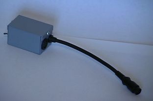
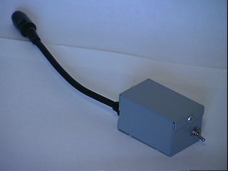
Here are two views of the B&W EVF adapter I built for my XL1. I did not include a switch to turn off the viewfinder CG lines, but that would be simple to add.

This box could be attached below the "Canon 3CCD Digital..." on the EVF assembly with velcro.

Tried a bowl of fruit (apples, pears, etc) for focusing with color and B&W, and can't say there was any significant difference. For most users, this project probably isn't worth the effort to do it.
The Watchdog notes: While there is no significant difference between the color and B&W viewfinder images, as Don has just pointed out, some shooters (especially the "old school pro" variety) may prefer a B&W image, because they perceive it to work better for manual focusing, exposure adjustment and other reasons. And although as yet unproven, it is entirely possible that the Sony RM-95 service remote, which is used by engineers to make and change internal camcorder settings, might be able to toggle the color and CG information on and off within the XL1's viewfinder. Hopefully that will be the subject of a future Watchdog article...
For now, as far as I know, Don is not interested in building these things for the XL1 public; after all, the man has to work for living. I suppose if there was an overwhelming interest, he might be persuaded to quit his day job, but I rather seriously doubt it. Instead, there might be a small company with some production capability or an engineering firm out there somewhere that might consider manufacturing these adapters. If so, Don gets a royalty!